
Concrete & Structural Imaging
Structural & Concrete Scanning Services in Oregon (Eugene & Portland) and Washington State (Everett, Renton, Seattle & Tacoma)
High Resolution Concrete and Structural Imaging Ground Penetrating Radar (GPR) is a Geophysical method that uses electromagnetic radar pulses to image concrete floors, walls, and ceilings. Concrete radar and location services are used to locate rebar, plastic conduits, metal conduits, reinforcing elements, empty conduits, wire mesh, estimate depth of post-tension cables, determine cover depth, detect deterioration, discover voids, detect current carrying cables, etc.
Design and Construction professionals involved in concrete/structural coring, cutting, and chipping now have a safe and reliable means of working in these environments: High resolution GPR concrete scanning. Construction records for many structures are not readily available and construction often differs from design, which means that GPR scanning concrete slabs is one of only a few methods available to assure what is inside of post tension slabs, precast slabs, flat slabs, ribbed slabs, decking slabs, one way joist slabs, hollow core slabs, waffle slabs, slabs on grade, post tensions slabs on grade, composite slabs, hardy slabs, concrete columns, concrete pillars, concrete footings, concrete beams, etc.
GPR can identify both metallic and non-metallic features making it a versatile concrete imaging tool. Concrete and structural imaging GPR is now widely used for assessing the interior of concrete structures. When cutting and coring for renovation and repair, avoiding reinforcing materials, such as post-tension cables, rebar, and embedded conduits is a priority. Knowing their precise location is critical for the operator and public safety. Post tension and rebar scanning services also ensures structural integrity.
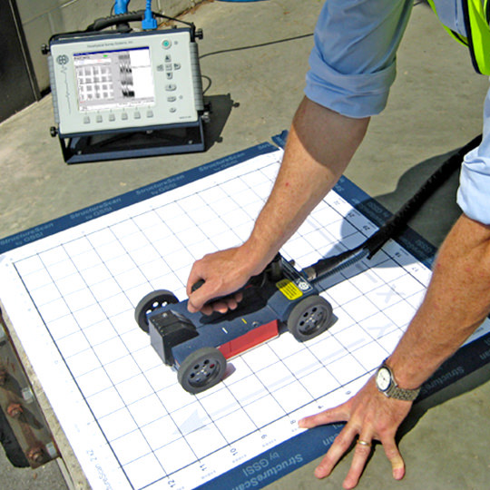
GPR scanning, performed by our NUCLA Certified Technicians, is safe because it emits no radiation and does not require the evacuation of the public and other personnel. A high resolution GPR monitor offers a detailed view of “what is within” and works in a fast reliable manner. This process yields real time results which are not possible with traditional radiographic (x-ray) methods. Our GPR concrete scanning antennas are highly portable and can be set up within minutes, even in locations with limited access. Our concrete scanning services are a non-destructive testing technology that benefits our clients as it allows them to execute their projects efficiently and effectively, saving them time and money.
The Concrete/Structural Imaging System offers a quick and efficient inspection of slabs, floors, ceilings, roofs, columns, beams, decks, encasements, pylons, balconies, bridges, tunnels and more. It is useful in penetrating and detecting the precise location of utility lines, pipes, conduits, rebar, post- tension cables, and other buried objects as well as determining the thickness of the material examined. The depth range of ground penetrating radar is limited by the electrical conductivity and the dielectric permittivity of the subject material, and the transmitting frequency. Higher frequencies do not penetrate as far as lower frequencies but give better resolution. Optimal depth penetration for GPR concrete scanning is achieved in dry, cured concrete where the depth of penetration is up to 18-24 inches. In moist and uncured concrete with high electrical conductivity, penetration is sometimes only a few inches. Data collected from a concrete scan is processed quickly and easily. The results produce and display a real time 2-D image and or a 3-D image (if requested) for a more intuitive approach to data analysis and interpretation.
Multiple viewing options allow the user to move around in the data, many times revealing features not visible in traditional vertical data profiles. A full report of a survey can be provided in two modes of acquisition: Line Scan and Grid Scan. Line scan displays section view data in real time mode. Grid Scan provides a rapid, intuitive collection of grid data that gets processed onboard to create 3-D plan maps. Data from both modes can be saved then copied to a compact flash memory card. Depth slice imaging can be provided at one inch intervals and all data can be viewed on a LCD color monitor, capable of displaying data in multiple color palettes.
When Should Concrete Be Scanned?
Locating Rebar | Locating Radiant Heat Pipe | Locating Pipes | Alterations |
|---|---|---|---|
Locating Post Tension Cables | Locating Plastic Pipes | Locating Concrete Footings | Renovations |
Locating Voids | Locating Conduits | Locating Grade Beams | New Construction |
Determining Slab, Wall and Ceiling Thickness | Locating A Clear Place to Core | Locating Concrete and Asphalt Thickness | Tenant Improvements |
Locating Concrete Deterioration | Locating Fiber Optics | Roadways | Research and Investigations |
Runways and Tarmacs | Bridge Decks | Tunnels | Seismic Modifications |
Garages | Retrofitting | Balconies | Surveying Prior to Design |
Walls and Columns | Towers | Monuments | |
3D Mapping of Interior Obstructions | Architectural Facade Inspection | Hydronic Lines |
Many people refer to GPR Concrete and Structural Scanning as concrete x-ray scanning, but this is incorrect. Concrete structural scanning with GPR and concrete x-ray scanning are very different technologies. X-ray technology poses serious health risks, requires stopping work in the area, and is not as fast, accurate, or efficient as concrete and structural imaging with GPR.
Concrete and Structural scanning radar technology is non-destructive, non-invasive, and additionally, it is more cost effective compared to the older x-ray technology. Our concrete slab scanning GPR technology can also scan slab on grade because only single sided access is necessary. Due to its portability factor, a GPR Concrete/Structure Scan allows us to collect large amounts of excellent onsite real time data in a relatively short period of time with color display and 3D imaging capabilities.
Advantages of GPR Over X-Ray
ADVANTAGE | X-Ray Radiography | GPR |
|---|---|---|
Your Cost | High | Low |
Access Required | 2 sides | 1 side |
Set-up Time | Long | Short |
Date Collection Speed | Slow | Fast |
Real-time Inspection Results | No | Yes |
Data Storage Medium | Film | Digital |
Consumable Required | Yes | No |
Licenses Required | Yes | No |
Hazards (radiation) | Yes | No |
Large Area Data Collection Method | Step and repeat | Continuous |
Must Process to Get Results | Yes | Optional |
Can Determine X-Y location | With calculations | Direct readout |
Can determine Exact Z (depth) Location | With calculation | Direct readout |
- Non-Destructive: Frequency waves inflict absolutely no damage on the subsurface, environment, or surrounding people.
- Disturbance-Free: Makes little noise and doesn’t bother surrounding people during use.
- Easily Deployed: Multiple size options that are user friendly, so it can be stored, moved, and utilized almost anywhere with few limitations.
- Rugged: GPR units are extremely durable and designed to endure the everyday tasks associated with its suitable applications.
- Multiple Applications: Ideal in most utility locating, underground locating, structural, archaeological, and concrete applications.
How Does It Work?
Can GPR See Through Everything?
What Can I Find With GPR?
Is GPR Safe?
Yes, GPR is extremely safe. It emits around 1% of the power of a typical cell phone.
How Deep Does It Go?
- Soil Type (Dielectric and Conductive Properties)
- Antenna Frequency
- Size and Material of the Target
Antenna Capabilities | |||
|---|---|---|---|
Antenna | Approx. Penetration in Dense Wet Clay | Approx. Penetration in Clean Dry Sand | Example of smallest visible object |
100 MHz | 20ft (6m) | 60ft+ (18m+) | Tunnel @ 60ft (18m) Depth2ft (60cm) Pipe @ 20ft (6m) Depth |
250 MHz | 13ft (4m) | 40ft (12m) | 3ft. (90cm) Pipe @ 12m6in. (15cm) Pipe @ 13ft (4m) |
500 MHz | 6ft. (1.8m) | 14.5ft. (4.4m) | 4in. (10cm) pipe @ 4m3/16 in. (0.5 cm) Hose 1.8m & Less |
1000 MHz | 3ft (90cm) | 6ft (1.8m) | 3/16 in. (0.5 cm) Hose @ 3ft. (90cm)Wire mesh, Shallow |
2000 MHz | .5 ft. (15cm) | 2ft. (60cm) | Monofilament Fishing Line |
250-800 MHz ground penetrating radar antennas are most widely used for locating subsurface utilities.
1000-2600 MHz ground penetrating radar antennas are most widely used for locating rebar, post tension cables, utilities, voids, and any other types of reinforcement in walls and floors.
How Accurate Is It?
What Do You See?
Understanding GPR Data
Planning A GPR Survey
Coverage
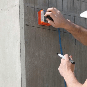
Concrete scanning can be carried out in a number of ways. Each method has its pros and cons while inevitably suiting certain situations best. Some of the most common methods of concrete scanning include:
- Ground Penetrating Radar (GPR)
- Ferroscan
- Ultrasound (Ultrasonic Tomography)
- Cover meter
- Concrete X-rays
