Ground Penetrating Radar
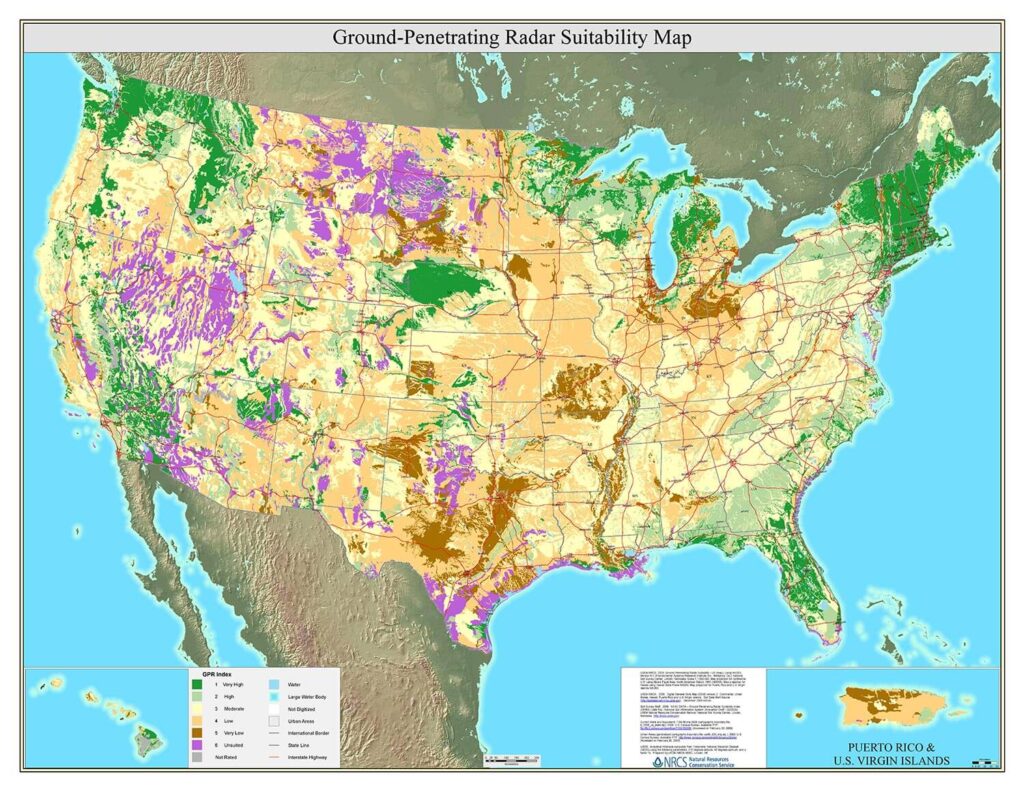
Ground Penetrating Radar (GPR) Detection in Oregon (Eugene & Portland) and Washington State (Everett, Renton, Seattle, & Tacoma)
RADAR (Radio Detection and Ranging) is a technology primarily used to detect above-ground objects such as aircrafts, ships, vehicles, birds, and rainstorms. In contrast, ground penetrating radar (GPR) antennas transmit an electromagnetic pulse into the ground, and when this pulse encounters a change in material or an object, it echoes back and is captured by the antenna’s receiver. The software used for ground penetrating radar utilizes the frequency and time delay of the transmitted pulses and received echoes to generate information about the target. The depth range and resolution depend on various factors such as radar frequency, transmitted power, the ground material’s dielectric/conductive properties, and the targets’ shape and characteristics.
There are three ways to perform a Dielectric Calibration:
- Educated Guess (being familiar with dielectric values of materials). This method typically has a 10-20% accuracy.
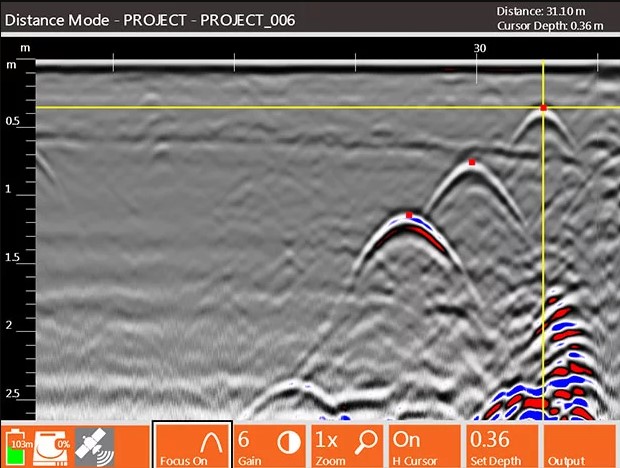
- Hyperbola Match (matching the shape of the hyperbola of the deepest object on the GPR image). This method typically has a 5-15% accuracy.
- Ground Truth (measuring the depth of a known target). This method typically has a 5-10% accuracy.
Changes in dielectric cannot be accounted for because only one dielectric value can be entered into the system at a time. Concrete tends to stay consistent, and soil can change horizontally and vertically.
Identifying Targets
GPR profiles were taken parallel and perpendicular to the drainage in the figures above, revealing a gradual increase in pipe depth from right to left of approximately 3ft (1m). The concrete storm drain’s top and bottom reflections were detected, indicating no metallic structure. Based on the reflection depths and assuming it was an air-filled pipe, the diameter was estimated to be 36 inches. The entire process of locating, marking, tracking depth, and diameter estimation took around 10 minutes.
GPR images can be color-coded using a specific color palette to assist identifying reflections of GPR signals, since some reflections can be more easily identified in different color palettes. Multiple color palettes are available for displaying the image, with some palettes providing better visualization of the target than others. (See Examples Below)
GPR – Locating Pipes & Cables
GPR – Subsurface Utility Mapping
GPR – Applications
- Utility – Identification of Metallic and Non-metallic, Metal Pipe, Clay Pipes, Concrete Pipe, Transite Pipe, Plastic or PVC Conduit, Cable or Wire, Duct Banks/Vaults and Manholes, Water Boxes, Abandoned Lines, Illegal or Unknown Connections, Fiber Optic Lines, Missing Valves, Septic Tanks and Septic Systems, and SUM/SUE Utility Mapping.
- Environmental – Identification of Underground Storage Tanks (UST’s), Landfill Limits, Rubble Limits, and High Saturation Levels.
- Road inspection – Identification of Reinforcing, Cracking, Voids, Water Infiltration, Concrete Sparling, Slab Thickness, and Asphalt Layer Thickness.
- Geophysical – Identification of Strata Layers, Ground Water, Root Mass, Disturbed Soil, Buried, Wood, Bedrock, Boulders and Rocks, Density Changes, and Fill Replacement.
- Archaeology – Identification of Artifact Locating, Structure Mapping, Cemeteries, and Unmarked Graves.
- Military – Identification of Unexploded Ordinance (UXO), Bunker Location, Tunnel Location, and Weapons Cache Location.
- Law Enforcement – Identification of Contraband Location, Objects Hidden in Walls, Buried Caches, and Materials for Forensic Investigations.
GPR – Facts
- Non-Destructive : Despite its name, ground penetrating radar (GPR) is a safe technique that emits only 1% of the power of a cellular phone signal. Its frequency waves do not harm the surrounding area's subsurface, environment, or people.
- Disturbance-Free : GPR generates minimal noise and causes no inconvenience to people in the vicinity while in use.
- Easily Deployed : GPR comes in various user-friendly sizes and is easy to store, transport, and use almost anywhere with few limitations.
- Multiple Applications : GPR is suitable for utility locating, underground locating, structural, archaeological, geophysical, environmental, military, and law enforcement applications.
- Various Strengths : CNI Locates GPR antennas range from 250 MHz to 2,600 MHz to match your specific application and depth requirements, up to 30 feet. Lower frequency antennas (250-800 MHz) are ideal for deeper utility scanning, while higher frequency antennas (1000-2600 MHz) are best for shallow concrete/structural scanning.
- Upgrade To Previous Methods : GPR provides a similar result to having a test trench or boring along the entire project without the need for unnecessary digging or potholing.
- Eliminates Waste : GPR identifies areas for test pits or sample bores instead of using the SWAG method, minimizing useless or misleading data.
- Easy To Read : The high resolution GPR interface allows easy navigation and displays clear image resolution of soil disturbance and other material compositions.
- Computer Friendly : Most ground penetrating radar systems include a USB port for easy transfer of data to printers, computers, memory sticks, and other devices.
- GPR Certification : All equipment complies with FCC, CE, and RSS-220 regulations. For more information, visit Regulatory Information. All CNI Locates GPR utility locators are NUCLA certified to perform ground penetrating radar services.
- GPS Integration : GPR systems can integrate with most GPS systems. The GPS position data files and GPR scans are automatically matched within systems to ensure proper GPS position data is recorded.

