Electrical Ground Fault Locating
Electrical Ground Fault Detection in Washington State (Everett, Renton, Seattle & Tacoma)
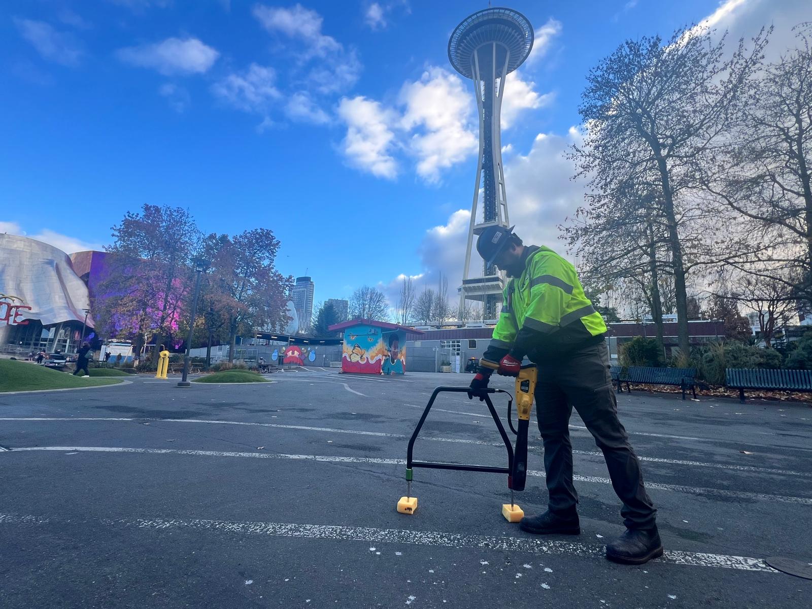
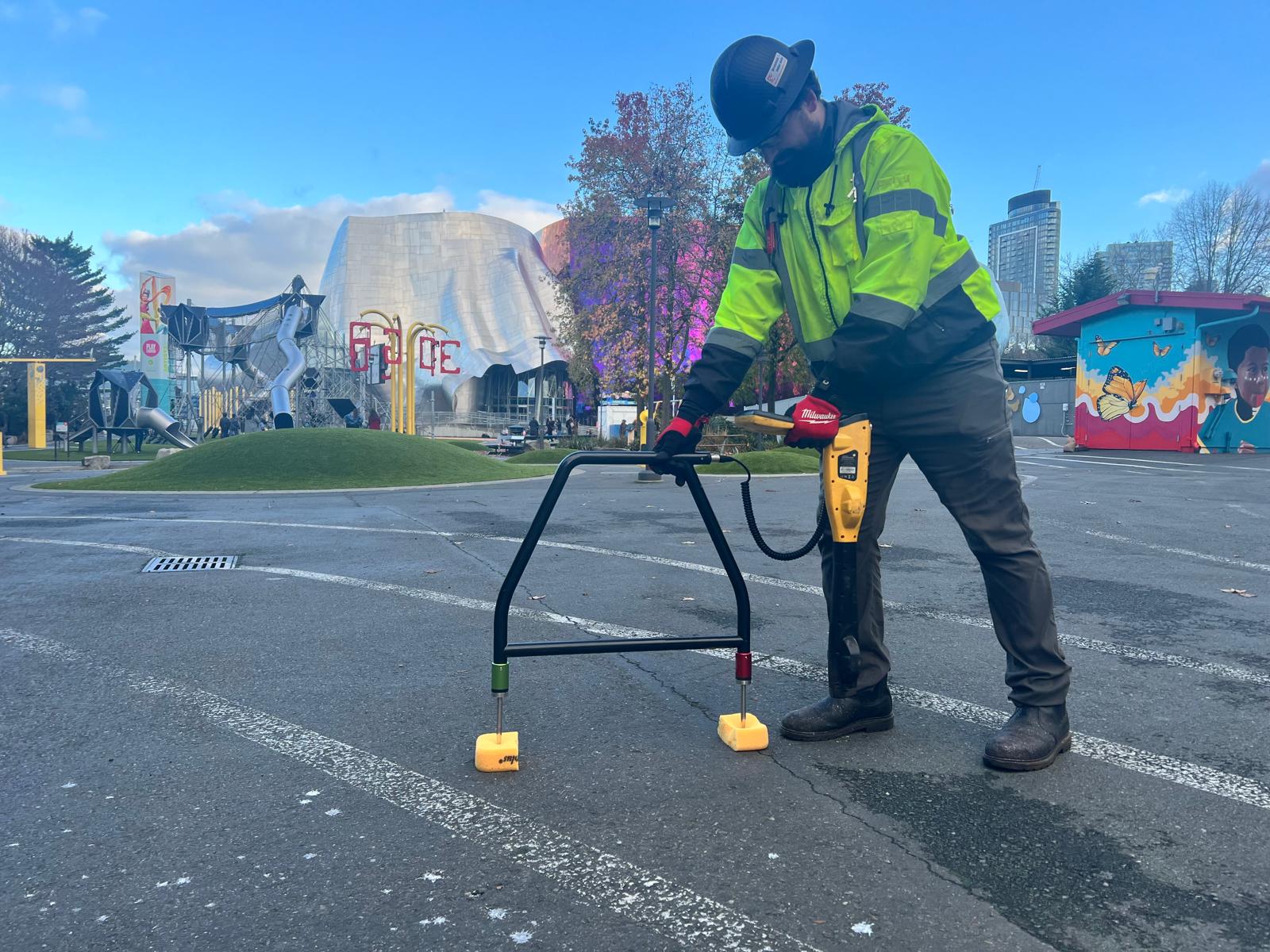
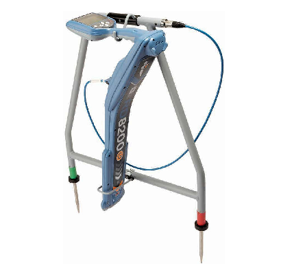
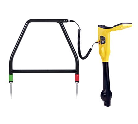
Identification of electrical ground faults, shorts, and opens are performed by a ground fault detection service. CNI Locates utilizes Multi Meters, Electromagnetic Transmitters, and Electromagnetic Receivers with A-frames to identify the precise location of electrical ground faults.
Buried cables occasionally fail for various reasons and in many different ways. Lightning strikes, overloads or surges, installation problems, and shovel and rodent damage are some of the common causes of damage that can lead to cable failure. In particular, any discontinuity in the cable jacket, which allows moisture over time, corrodes the conductors. Cables fail either open circuit, short circuit, or somewhere in between, to earth and/or to another conductor in the cable. The type of fault should be determined as different faults require different approaches. For that, a persistent fault to earth (a ground fault) is usually most accurately and most easily found with an A-frame. Open and short circuits are best found with a TDR, and a ‘flashing’ fault that only happens at high voltages usually requires a high voltage surge generator or ‘thumper.’ Most transmitters in a fault-finding system will have some way to indicate if there is a path to ground, such as an ammeter or ohmmeter, and some have both. If there is a path to earth, the A-frame is still one of the most popular and recommended methods suggested by a ground fault detection service when the conductor is not enclosed in the duct.
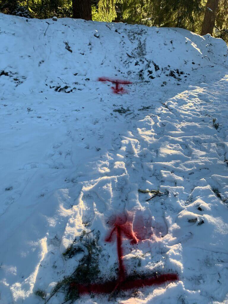
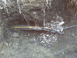
Location of fault
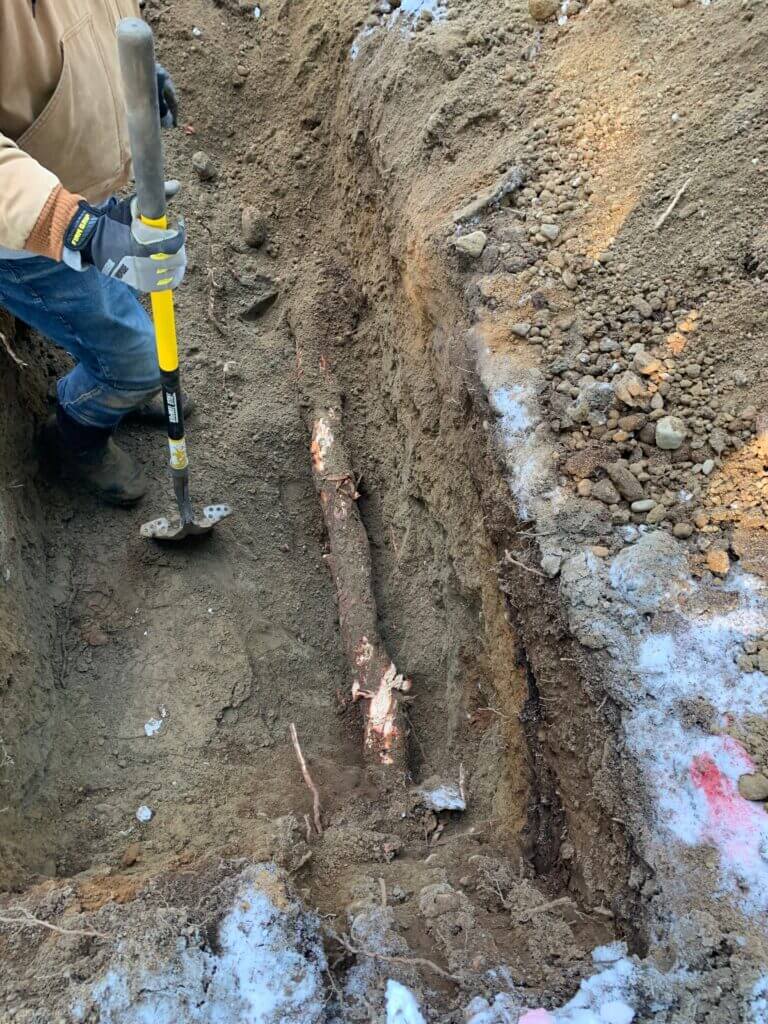
Root grew around the wire
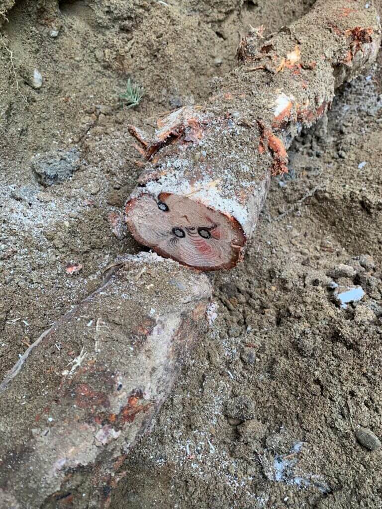
Fault inside of the root
We can build on the methods of basic locating to detect persistent earth faults. We showed that cable locating is achieved by creating an alternating current (AC) on a cable and tracing the resulting AC electromagnetic (EM) field with a tuned receiver. A-frame systems differ in that, in addition to the locate signal, we add a pulsed DC current (for ground fault locating) to the cable under test (CUT). DC allows the detection of the current direction and will lead the user toward a fault. Where there is contact with the earth, this current will flow out of the CUT at fault and back to the ground stake of the transmitter. The current will be concentrated near the fault(s), and the ground stake but from those points will travel very wide and deep in search of the path of least resistance. Current through a resistance makes a voltage. The flow of the pulsed DC through the impedance of the earth will create a slight DC voltage, and that is how we find faults. The addition of an A-frame to an electromagnetic locator basically turns the locator into a very sensitive voltmeter, and following the pulsing DC through the earth with the A-frame gives a direction to and magnitude of the fault(s).
Because we follow the path of current through the earth, cables inside of duct banks cause us problems. Even if we have fault finding signal flow, it doesn’t necessarily lead us to the fault. If the cable problem happens to be at the point of duct damage, we may have sufficient current flow through the earth from that location. Quite possible, though, is that there is moisture inside the duct, and we are getting some current flow through that path as well, limiting the signal that leads us to the fault. If the cable problem is entirely within a good duct (such as happens when a jacket gets skinned while pulling it into the duct), all of our current flow can be inside the duct until a path to ground is reached (such as at a defective duct joint), and we can’t find the fault. At best, we can find where the moisture inside the duct is coming into contact with the earth, such as at a bad joint.
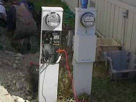
Proper setup for fault detection services and use of an A-frame system requires that we prevent the fault locate current from getting to earth anywhere other than at the fault(s). It ensures there is a maximum amount of signal to follow, and it will lead us to the right position. As such, all other paths to the ground, including neutrals and ground wires, have to be disconnected. Power cables must be taken completely out of service before testing for faults.
The use of a good earth ground is even more important when fault finding than it is with regular cable locating. An extra spool of ground wire with a large clip on end is a valuable tool, allowing the use of distant, independent ground stakes. Stop signs, insulated anchors, and existing but isolated ground stakes will often improve the performance of locating equipment. The practical limits of fault detection are around 0.5-2 M W of DC resistance, depending on ground conditions. Since the A-frame measures voltage, it needs to have electrical contact with the earth under it. Concrete, asphalt, and dry or sandy soil are all high-resistance paths to the ground and can limit the voltage fault detection can detect through the ground. Sometimes, wetting down the ground and even the pavement in the path of the target conductor will assist in fault detection. Better yet, if there is access to the unpaved ground running parallel to the target conductor, the A-frame may be used even if it is several meters off to one side.
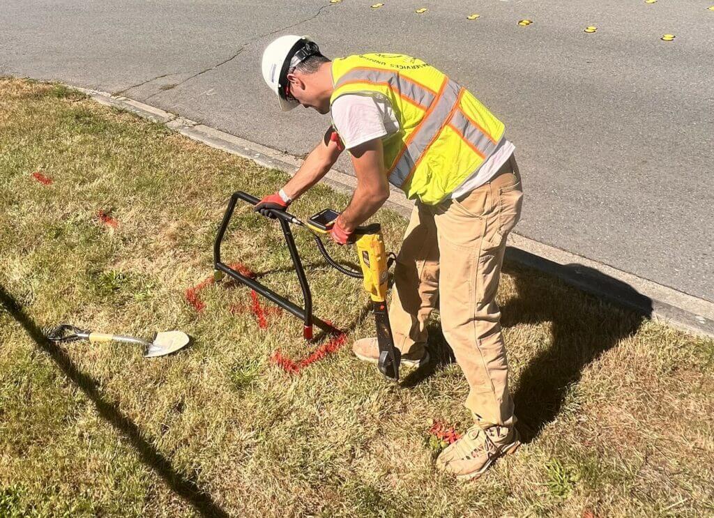
After we have determined it is an earth fault and there is sufficiently low resistance to detect its position, we can start walking the cable path with the a-frame. There are two indications on most a-frame systems; signal strength and fault direction. The signal strength is best shown as a logarithmic value, as there is a huge range of signals that can be detected. The receiver should indicate a large fault magnitude close to the ground stake where there is a concentration of current. It is a good idea to remember this value as a ‘reference number.’ The value of the detected current (reference number) should also be indicated at the fault location. Most ground fault detection service companies recommend that the A-frame be placed in the ground approximately the same distance away from the ground stake (in the direction opposite of the actual cable path) as the cable is deep, to get this initial fault magnitude reference.
Between the fault and transmitter, the magnitude will drop, often substantially, as the current has spread out so far as thus become ‘diluted.’ The behavior of the arrows may also change. Near the fault and the ground stake, they will exhibit a good hard ‘lock’ on the fault direction, but in the middle of the cable span, the weaker signal can result in fluctuations or no direction indication. The proper technique is to keep walking through the weak area, and as we approach the fault, the signal will increase, and normal operation will resume.
A ground fault detection service detects a fault when two things happen; the signal strength increases due to the increased current concentration as we approach the fault, and the arrows suddenly reverse as we cross over the fault. Turning the a-frame 90 degrees and crossing the cable path will add more accuracy to the fault location. A final test of the fault location is to perform a ‘pothole’ or circle of the fault. Leave the front leg of the a-frame in the ground, directly over where the fault is believed to be, and circle that point, placing the back leg in the ground at several points on the circle. If all signal indications point toward the stationary leg, we have found the best location. Suppose the number in the receiver at this location does not reflect the reference number you saw back at the transmitter’s ground stake. In that case, you have an indication there may be more faults on this cable (or the cable depth is different than you expected).
If possible, excavate the fault, fix it, or at least remove its contact with the earth and retest the cable with the ohmmeter function. Removing all contact includes drying the outside of the cable to prevent a current path through the moisture. If the cable now tests well, we can be confident there are no other faults on the cable.
Unjacketed concentric neutrals can pose a problem as our fault location current sometimes finds the neutral an easier path back to the area of the ground stake than the earth. This effect can be minimized by placing the ground stake as far away from the cable as possible and using a very good (low resistance) ground.
A ground fault detection services A-frame is the most accurate but not necessarily the fastest tool to use, as the operator has to walk the cable length from the transmitter to the ground fault. Often an earth fault has let in water, and the conductors have also corroded open or short circuited. Using a Time Domain Reflectometer to estimate the rough location of a fault before the A-frame to find the exact point will often give the most efficient use of the technician’s time.
